PV System: 5. Electrical
Summary
Each solar panel produces DC voltage which goes into a separate micro-inverter for each solar panel. The microinverter converts the DC voltage into AC voltage. The micro-inverters are chained together and run into a junction box where it then connects to 14 gauge wires that run to the disconnect switch. Then the wires run from disconnect switch to dual 15A circuit breakers on the main panel.
Materials Needed:
The following are things you need to buy that don’t come in the kit:
- 14 gauge wires – to connect from the junction box to the disconnect switch. The gauge of wire to use depends on the distance that you need to run. The lower the gauge the thicker the wire. Thicker wires are harder to bend through the conduits (See F-UP #2 below).
- junction box – this is where the wires from the microinverters are connected to the 14 gauge wires and are protected from the wind, rain, sun.
- disconnect switch – don’t need a fused disconnect because the circuit breakers act as your fuse.
- 15A circuit breakers – dual 15A circuit breakers, your system may require different sizing. look at your wiring diagram that came with your kit.
- electrical conduit – to protect the wires so it isn’t exposed to the rain, wind, sun. There are different kinds of conduit you can buy, metal or PVC. I chose PVC because they are cheaper and easier to cut.
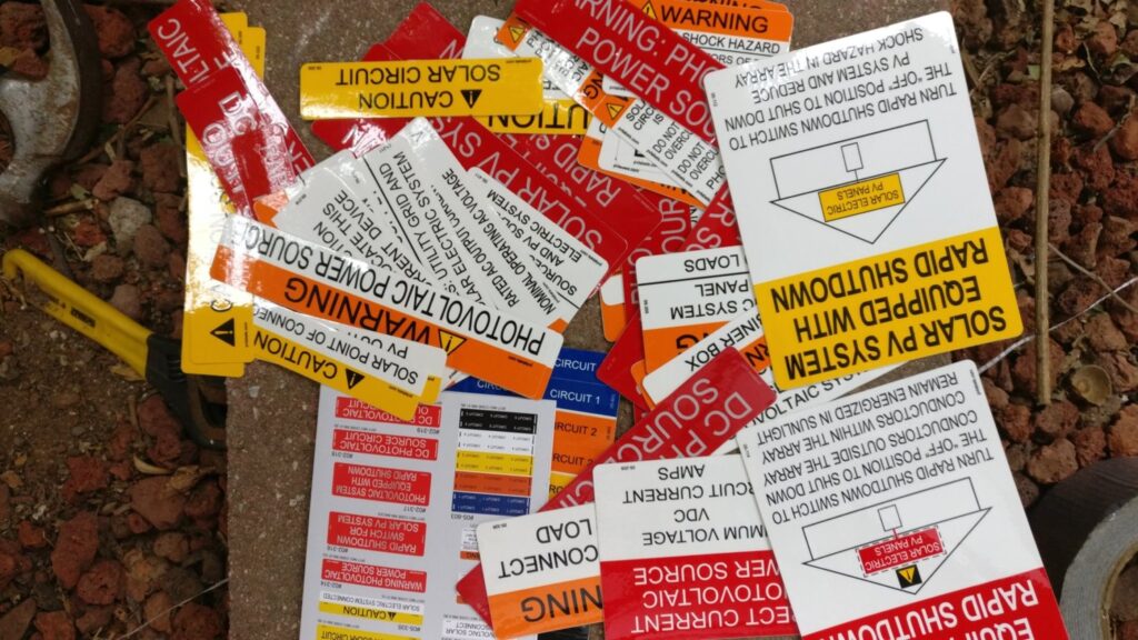
What does come in the kit is lots of stickers. About 200 more than you actually need.
Wiring the Microinverters
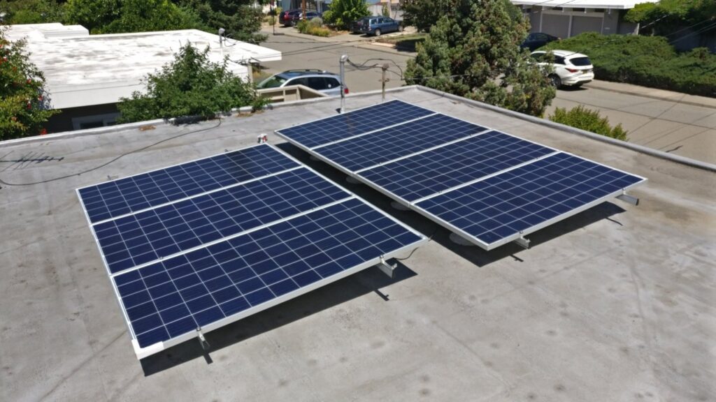
There are 7 microinverters, one for each panel. They attach to the rail and are under the panels
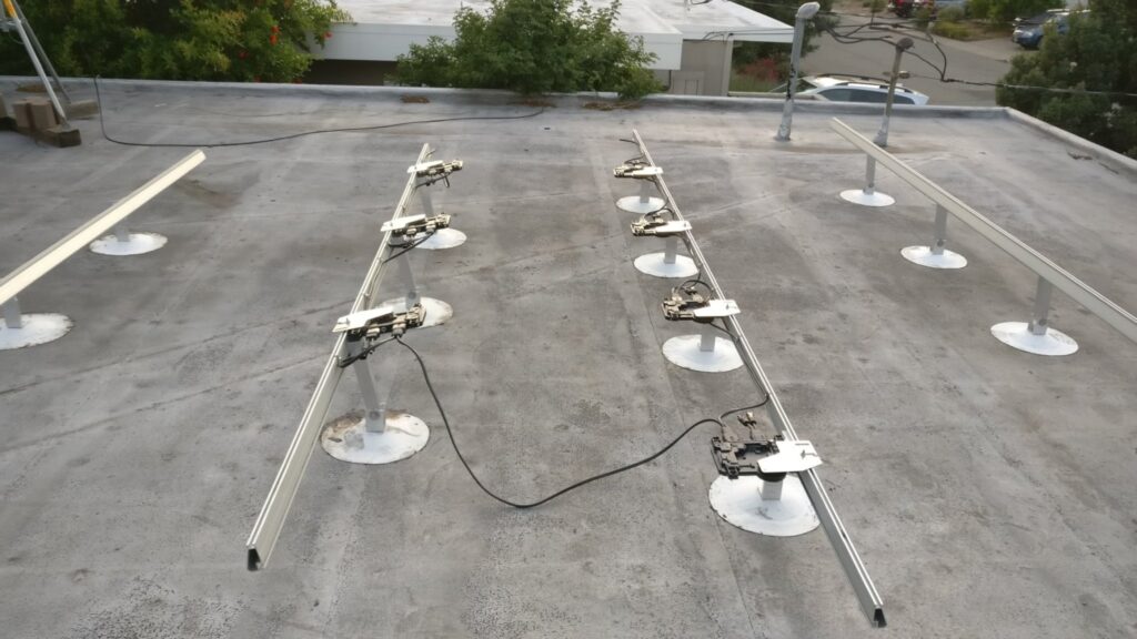
Install the solar panels on the rails. Don’t connect the panels to the microinverters until the very end. This will minimize the chances of electrocuting yourself.
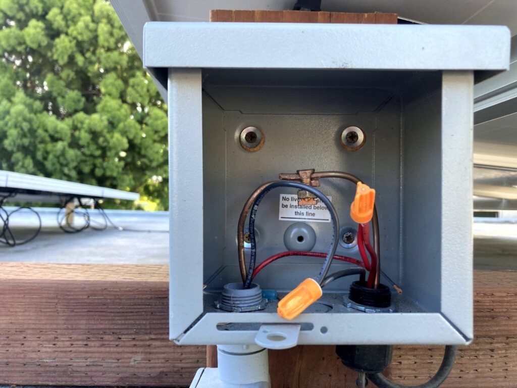
Junction Box
Mounted the junction box on a 4×4 post. You can see the black wire from the microinverter, which will go into the hole on the right bottom of the junction box. Then it will connect to the wire and run out the left hole.
Disconnect switch
Then run the wire from the junction box to the disconnect switch. Here is where I F’ED UP. I installed these right angle joints on the conduit and glued them together before running the wires through them. Then when I tried to push the copper 6 gauge wires it was too thick to bend around the corners. The 14 gauge wire was easy to bend. But the 6 gauge was unbendable. The solution was to cut the wire, run it from opposite ends and then join them together in the middle. What I should have done was to run the wire through all the pieces before connecting all the joints together.
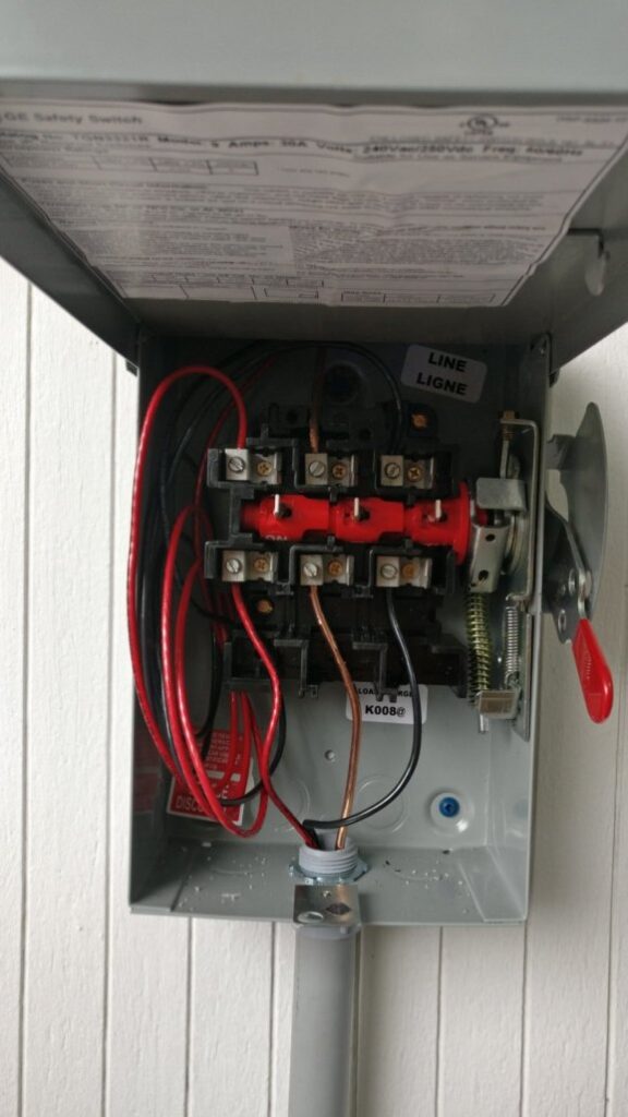
The wire then comes into the disconnect at the top. And then another set of wires run from the bottom out of the disconnect switch. Keep the switch disconnected.

Can you see where I F’ED UP in the picture above? The inspector looked at this failed my inspection. The problem is the copper ground wire in the middle. The ground wire should always be connected at all times. But I wired the ground into the switch. Below is the proper wiring with the ground wire always connected to ground.
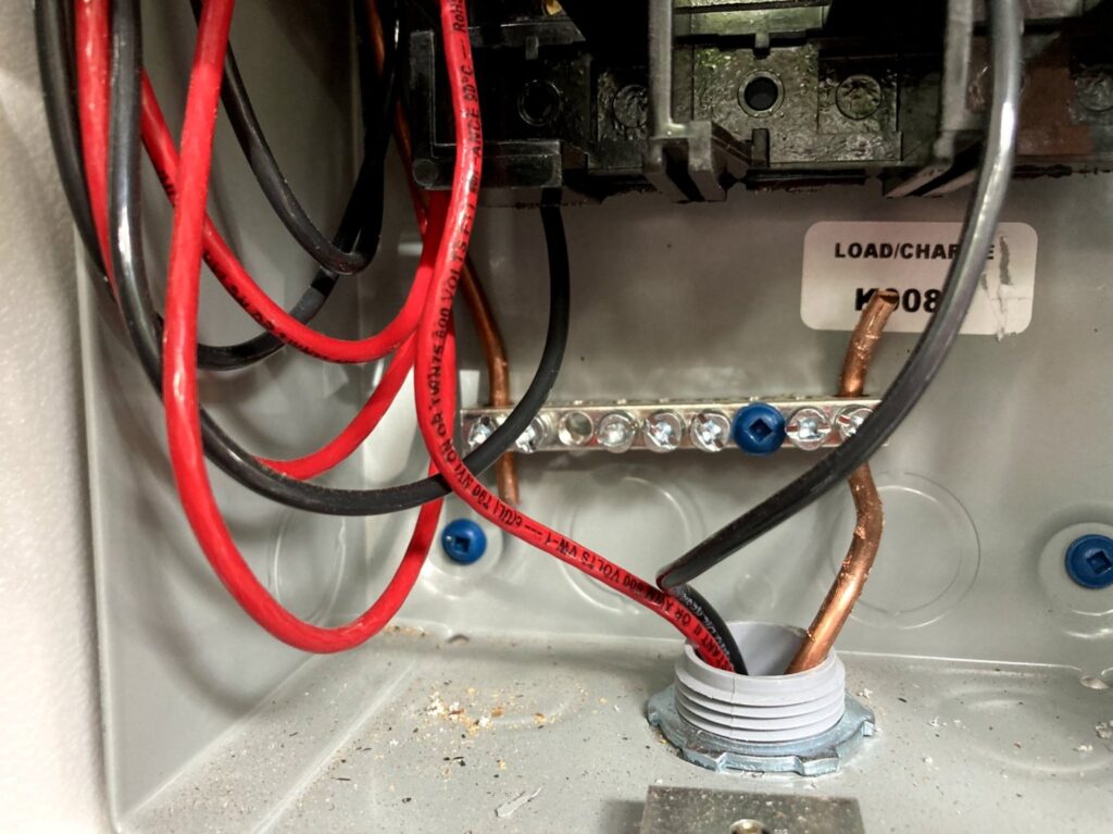
Main Panel
The wire from the disconnect then runs into the main panel. The main panel needs to be able to support 220V. I had a couple of different solar companies come out to give me a quote and consultation. They can confirm if you need to upgrade your main panel or if it is sufficient to support a solar system.
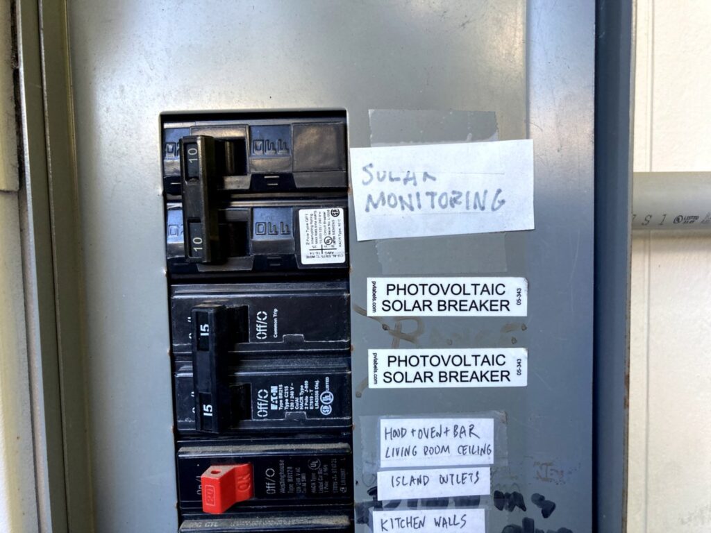
Dual 15A circuit breakers with nice label. The black wire runs into one of the circuit breaker. The red wire runs into the other. Doesn’t matter which one goes to which one. Remember to use the right size circuit breakers stated on your wiring diagram. I was lucky that I had two free spaces left on my main panel. I had to move some things around to get two spaces together.
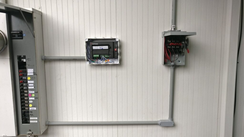
In order to monitor how much electricity your system is producing you need to run the wires through the production meter (comes with kit). More on how to setup the production and consumption meters (See 6. Monitoring).
Grounding
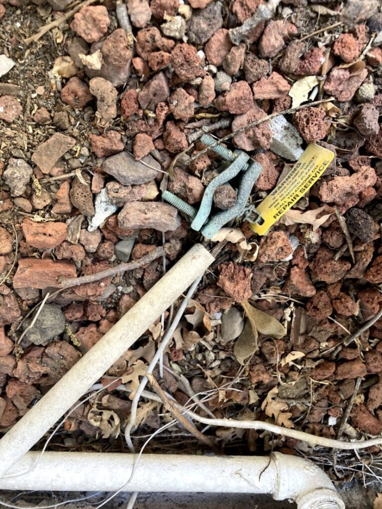
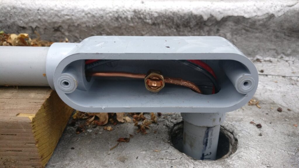
The two arrays need to be bonded together with a ground. The picture below shows one array with the ground lug. This is connected to the other array with a similar ground lug.
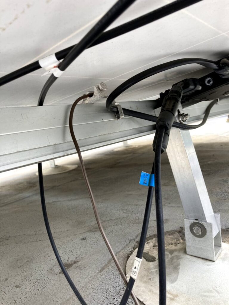
The ground wire runs through the disconnect and to the main panel where it is grounded with all the other grounds. Then the ground is bonded to the grounding rod.
